Home/
Unlabelled
/555 Timer Schematic Diagram - 555 Timer Projects For Beginners Diy Electronics Projects - Introduced in 1972, the 555 timer ic is still in widespread use due to its very low price and stability.
555 Timer Schematic Diagram - 555 Timer Projects For Beginners Diy Electronics Projects - Introduced in 1972, the 555 timer ic is still in widespread use due to its very low price and stability.
555 Timer Schematic Diagram - 555 Timer Projects For Beginners Diy Electronics Projects - Introduced in 1972, the 555 timer ic is still in widespread use due to its very low price and stability.. There are simple circuits for beginners and advanced engineers. The 555 timer can be obtained very cheaply from pretty much any electronic retailer. 555 timer, as the name specified, are the electronics circuits used for measuring time intervals.in this article, we will cover about 555 timers. However, the circuit will create sound when light falls on the surface of the ldr. 555 timer circuit | circuit diagram.
Must read 555 timer full tutorial. Lm555 timer 1 features 3 description the lm555 is a highly stable device for generating 1• direct replacement for se555/ne555 accurate time delays or oscillation. The reset input current draw illustrates the need for a current limiting resistor as shown in some of the preceding circuits. These on off intervals can be adjusted by varying the 555 timer output and number of counter outputs. The 555 ic timer circuit above shows a very straightforward design where the ic 555 forms the central controlling part of the circuit.
1 from The 555 timer ic is an integrated circuit used in a variety of time, pulse generation, and oscillator applications. The clock circuit that will produce 60hz clock signals using a 555 timer is shown below. This circuit uses very basic components like 555 timer and 4017 counter. Astable mode can produce digital square waveforms that go back and forth between high and low. The 555 timer has three operating modes, bistable, monostable and astable mode. So we have a signal with a frequency of about 60hz. Ne555 is a famous ic comes in 8 pin dip plastic package. The green light time can be varied by changing the value of capacitor.
The 555 ic timer circuit above shows a very straightforward design where the ic 555 forms the central controlling part of the circuit.
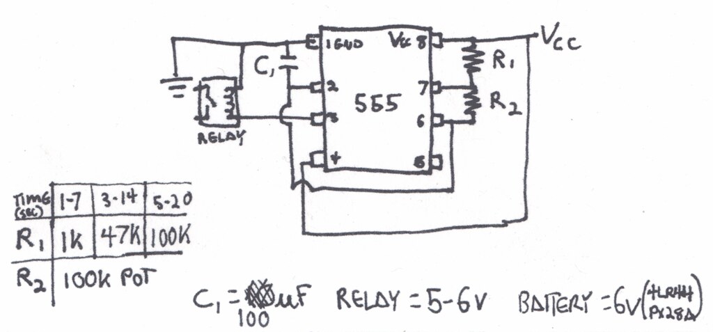
So, before implementing your 555 ic in any project, make sure that your ic is good or bad. Derivatives provide two or four timing circuits in one package.it was commercialized in 1972 by signetics. These on off intervals can be adjusted by varying the 555 timer output and number of counter outputs. Working modes of 555 timer ic. Introduced in 1972, the 555 timer ic is still in widespread use due to its very low price and stability. The circuit implemented in this project is basically an astable mode of operation of the 555 timer ic. All we need to change the value of resistor r1 and/or capacitor c1. If you want to know all the pinout of the 555 timer, what each pin is and what each pin does, see 555 timer pinout. The 555 timer is a simple integrated circuit that can be used to make many different electronic circuits. Adjustable on off timer(using 555 astable mode) in this circuit a timer with cyclic on off operations is designed. As discussed in the above section, the ic is in its standard monostable mode. The green light time can be varied by changing the value of capacitor. Working time is determined by the 220k potentiometer and capacitor c1.
As discussed in the above section, the ic is in its standard monostable mode. The 555 timer can be obtained very cheaply from pretty much any electronic retailer. The 555 timer ic is an integrated circuit (chip) used in a variety of timer, delay, pulse generation, and oscillator applications. Ne555 is a famous ic comes in 8 pin dip plastic package. For 5 min, 10 min and 15 min you just have to change the resistor value (r 1).
555 Timer Delay Off Circuit With Circuit Diagram 555 Timer Projects Youtube from i.ytimg.com We can use this property of 555 timer to create various timer circuits like 1 minute timer circuit, 5 minute timer circuit, 10 minute timer circuit, 15 minute timer circuit, etc. Some devices will not function properly if the current to the threshold input is not restricted. The breadboard schematic of the above circuit is shown below. Furthermore, the core of the circuit is a renowned 555 timer ic that wire as an astable multivibrator in the circuit. In this mode, the circuit of the ic 555 timer produces the continuous pulses with exact frequency primarily based on the value of the two resistors and. In monostable mode, the duration for. Although the schematic looks correct, this basic circuit may actually have a few negative aspects. The 555 timer, designed by hans camenzind in 1971, can be found in many electronic devices starting from toys and kitchen appliances to even a spacecraft.
Before going into detail of time delay circuit, first we need to learn about 555 timer ic first.below you can find the pin diagram of 555 timer ic along with the details of each pin.
The 555 timer starts timing when switched on. A collection of 555 circuits using the 555 timer as an astable oscillator with different duty cycles. All we need to change the value of resistor r1 and/or capacitor c1. 555 timer circuit | circuit diagram. Astable mode can produce digital square waveforms that go back and forth between high and low. In monostable mode, the duration for. There is a huge list of 555 ic circuits due to which this ic is very popular among electronics hobbiests, students and experimenters. 555 timer was first introduced by signetics corporation in 1971 as se555/ne555. The circuit implemented in this project is basically an astable mode of operation of the 555 timer ic. 555 timers are very popular in electronics. There are millions of 555 timer circuit schematic diagrams out there that can be found by doing a google search. Each mode of operation indicates a circuit diagram and its output. The values of r1 and c1 determine how long the output will remain high.
In this mode, the circuit of the ic 555 timer produces the continuous pulses with exact frequency primarily based on the value of the two resistors and. Its name is derived from three 5k ohm resistors ,connected in series used in it.the timer ic can produce required waveform accurately. The reset input current draw illustrates the need for a current limiting resistor as shown in some of the preceding circuits. There are millions of 555 timer circuit schematic diagrams out there that can be found by doing a google search. There are simple circuits for beginners and advanced engineers.
555 Timer Circuit Diagram Circuit Diagram And Parts Consid Flickr from live.staticflickr.com In monostable mode, the duration for. 555 ic timer block diagram 555 ic timer block diagram. Once this switch is pushed, the circuit pulls its output to a. The 555 timer ic is an integrated circuit (chip) used in a variety of timer, delay, pulse generation, and oscillator applications. Ne555 is a famous ic comes in 8 pin dip plastic package. When triggered by a button integrated in the circuit relay 555 timer is energized and immediately set is full when you leave the ignition again. The 555 timer ic is an integrated circuit used in a variety of time, pulse generation, and oscillator applications. There is a huge list of 555 ic circuits due to which this ic is very popular among electronics hobbiests, students and experimenters.
Traffic light electronics project with a 555 timer from www.circuitspecialists.com this article describes a project of a traffic light using 555 timer…
The 555 timer has three operating modes, bistable, monostable and astable mode. 555 timer was first introduced by signetics corporation in 1971 as se555/ne555. The second 555 timer helper will extend the timers output duration without having to use large values of r1 and/or c1. With this information you will learn how how the 555 works and will have the experience to build some of the circuits below. The 555 timer is a simple integrated circuit that can be used to make many different electronic circuits. Its name is derived from three 5k ohm resistors ,connected in series used in it.the timer ic can produce required waveform accurately. The next diagram shows the basic current consumption of 555 timer chips from different manufacturers. The working modes of a 555 timer are astable, bistable, and monostable. The circuit implemented in this project is basically an astable mode of operation of the 555 timer ic. 10+ traffic light using 555 timer. Simple 555 timer circuits & projects. So we have a signal with a frequency of about 60hz. The 555 timer can be obtained very cheaply from pretty much any electronic retailer.
555 Timer Schematic Diagram - 555 Timer Projects For Beginners Diy Electronics Projects - Introduced in 1972, the 555 timer ic is still in widespread use due to its very low price and stability.
Reviewed by MaXenzy
on
Juni 29, 2021
Rating: 5

 Reviewed by MaXenzy
on
Juni 29, 2021
Rating:
Reviewed by MaXenzy
on
Juni 29, 2021
Rating:


Post a Comment